Unfortunately, it looks like solid, usable improvements to the Attachment Editor are unlikely to be ready for a PR
by the end of my GSoC, although I will publish my experimental branch which uses Python for the datum tools and uses the Python-based
Attachment Editor I mentioned previously.
However, as a consolation I did finalize some additional tests for PartDesign Hole, so my goal of functional coverage of the PartDesign tools
succeeded.
Also, I think with this foray into GUI code, I've hit nearly the full stack of libraries used in FreeCAD this summer. It feels pretty nice, because
I feel prepared to tackle whatever problem I want to in the FreeCAD project.
The final portion of GSoC for me will be dedicated to working on improvements to the Attachment Editor, and this post will essentially be my design
for what those improvements will look like. The Attachment Editor is available in the Part Workbench through Python. One can for example create a simple
Part Cube, select it, then click Part -> Attachment. It also is used when creating datum geometry in Part Design, or when creating a primitive.
Here are a few screenshots:
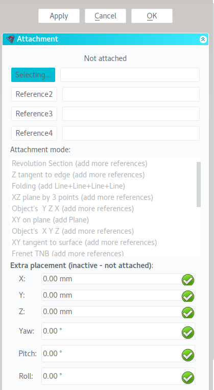
Figure 1. The Python-based Attachment Editor in the Part workbench.
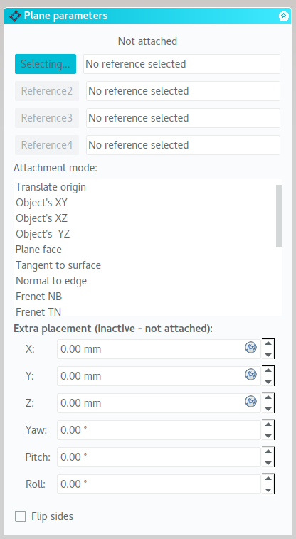
Figure 2. Creating a Datum Plane.
Creating datum geometry is a key part of the Part Design process, so it's helpful for it to be very easy and intuitive. The current
Attachment Mode information especially can be quite overwhelming to a beginner, however. Especially considering how improvements
to the Attachment Editor could be reused in a future Assembly Workbench, it was decided to look into improving these tools.
The first, most obvious improvement here would be inactivating the "Extra placement" section when inactive. This could
possibly be accomplished by making a separate collapsible section which automatically hides when there is no attachment.
The second, and tougher improvement, involves reworking the current the four attachment selections and the attachment mode.
Reference names probably don't need to be more than 3/4ths the width of the page. The methods for selecting references via
an activation button, and deleting via clearing out the text are not user-friendly.
The four-reference list here would ideally be replaced with an icon-based grid, which starts out empty. Each selection's icon would
be based on its type, e.g. Vertex, Edge, Face, Curve, etc., where available, and a generic icon for unrecognized types. The selection's name
could be displayed in a shortened form, e.g. "MyLongShapeNameIs...". This approach could be extended for future Assembly use by adding a scrollbar
on the icons, allowing for several rows of attachment references, 4 at a time.
This tool could be very user-friendly, as invalid reference icons can be highlighted red, and when the attachment is complete, the reference set's icons
can be highlighted green. Ghosted icons can be displayed as needed for a selected Attachment Mode.
A similar approach for Attachment Mode could be used. Using a 4-icon row with a scrollbar, attachment modes can be explained with a short label and
an icon, where feasible; hopefully the large size will allow for expressive icons. When a mode is moused over or selected, the remaining references required
can be displayed in the reference selection area.
Altogether, (i) splitting out the placement and toggling when it has no effect (i.e. there is no attachment) and (ii) reworking Reference Selection and Attachment Mode
dialogs to use unified icon list GUI code, as well as (iii) making the icon set to explain the attachment concepts to users, comprise the components of this
"Attachment Editor Improvement" project.
I celebrated my birthday in south Texas last week! I was about 3 miles from the future SpaceX launch facility opening in 2018.
It'll be great to possibly see launches to Mars from there in the next few years.
I mostly spent this week working on the bugs I mentioned last week. I wanted to try to make a dent in the outstanding bugs I've found.
Unfortunately, my lack of C++ background (compared to Python) really hampered this; it's a little bit like trying to run before you walk.
In the end, I only fixed the Revolution bug(s). In the case where a revolution is attempted on the same plane as the sketch, resulting in e.g. a flat disc,
the issue was that the code was checking the angle between the sketch's normal and the revolution plane's normal, looking for a 0° angle. However,
it was failing to fail in the case of a 180° angle.
I also added a simple convenience check for all tools in Part Design: if you open a document with only one body and try to click a PDN tool's button,
the single body will be auto-activated instead of popping up a warning. If there are no bodies or more than one, the warning still occurs.
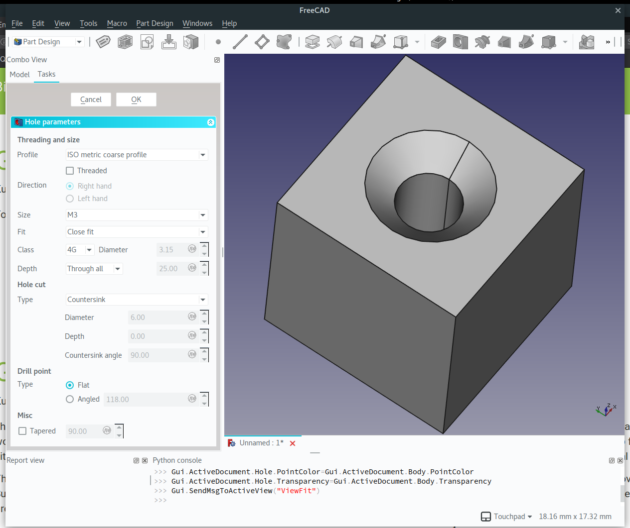
Total tool coverage lasted less than a week! It's a good thing though, because that means a new tool landed in master: PartDesign Hole.
This is a really great tool for the Part Design WB not only because holes (and their corresponding fasteners) are ubiquitous in part design generally,
but also because the tool does a good job of capturing that information into a FreeCAD object that can be later be hooked into for both the
Assembly and TechDraw workbenches. For example, the options I've selected in the following screenshot could be used to complete a technical drawing
for this part in FreeCAD, and that information exchange could be done in an automated and customizable way.
This information could also be used by the Path WB to generate control code for open-source, automated manufacturing processes and machines, so it's really
great to have such a full-featured tool added.
I spent some time trying to find bugs in the tool, but didn't really find any. The only gotcha I noticed is related to the orientation of sketches which serve as the
basis for holes. There is no Reverse option for the Hole feature itself, so for example, if you have a sketch on the "bottom" of an object but not attached to it,
you may need to set the Map Reversed option for the sketch itself to true.
Some tests will be forthcoming for Hole, but besides that, I also spent some time looking at few outstanding bugs in C++-land.
Particularly,
(mentioned in week 5) ShapeBinder crash when base object not initially selected due to null pointer dereference
(mentioned in week 3) Revolution has unhandled error for some bad revolution axis choices, does bad revolution without error for others
(new) Pipe fails when its path is a loop. For example, a Pipe with a circle as a base and a larger, orthogonal circle passing through the base should become a torus.
Currently, it fails with the wonderfully verbose error message 'TopoDS::Shell'.
I hit a nice milestone this week! With PR 899 I hit total tool test coverage for the Part Design workbench.
Now, what exactly does that mean? Well, if you look at my screenshot of the workbench tools from Week 2, every one of those is now covered by tests with most
key functionality hit. Some of them, like the dressup features Fillet and Chamfer, only have one test, either because the tool is simple or because further tests
lie outside the scope of the Part Design workbench (e.g. testing the topological naming robustness of Fillet to recalculation.)
The PartDesign Primitive (Box, Cylinder, Sphere, Cone, Ellipsoid, Torus, Prism, and Wedge) tests were interesting to write.
I was able to cover basic construction of both Additive and Subtractive primitives of each type by simply making a large Additive Primitive
and smaller Subtractive Primitive inside the first, and then ensuring that the ensuing Shape's Volume property was about equal to
the difference in volumes according to the formula for that shape, e.g.
\[
\mathrm{Shape.Volume}\ \approx V = \frac{4}{3}\pi (R^3 - r^3)
\]
for Additive-\(R\) and Subtractive-\(r\) Primitive Spheres.
I had to look up a few volume formulas but otherwise the tests for the lengthly list in the parentheses above went quickly.
I also fixed a bug with Loft sections not being hidden, so e.g. the Sketches being lofted to or through were still visible.
Additionally, there was an issue with both Loft and Pipe not claiming children correctly in the tree which I fixed.
Short post this week! I was in Spokane, Washington, from July 15-19th for a robotics competition being held at the Annual International Meeting of my professional society,
the American Society of Agricultural & Biological Engineers, or ASABE. I only had a smattering of time to work on the various FreeCAD bugs I have mentioned in previous posts
so there isn't much to report on that front. Instead, I'll leave a picture from the beautiful Spokane downtown area.
This week started out with some interesting discussions on the future Python structure of FreeCAD, over
on the forums. This was especially salient
as I have a bit of pain interacting with parts of the FreeCAD Python API and improvements to it would
be a good long-term goal after finishing GSoC.
I decided that the TestPartDesignApp.py file I had been working in thus far needed splitting up,
as I was cramming almost every new test into it.
The new version of this file
is a pretty nice indicator of the overall status of PartDesign test coverage.
I also added some basic tests for datum tools, covering simple creation scenarios. While exploring the 4th datum
tool, ShapeBinder, I found a bug that causes a crash, so I will need to look into that shortly to see if it's an
easy fix.
LinearPattern and PolarPattern got 6 new tests each, covering all the major variations of sketch-
or primitive-based features.
Finally, I added one new test for each of the dressup features, Fillet, Chamfer, Draft, and Thickness.
I started this week out with the goal of troubleshooting the bugs I found with PartDesign Pipe and Revolve.
However, I ended up running into several annoying issues. The LLDB debugging integration I previously wrote about
began showing some inexplicable errors:
error caught in async handler 'exec ('continue',)'
Traceback (most recent call last):
  File "/home/kurt/.config/nvim/bundles/repos/github.com/dbgx/lldb.nvim/rplugin/python/lldb_nvim/__init_
_.py", line 49, in _exec
    self.ctrl.safe_execute(args)
  File "/home/kurt/.config/nvim/bundles/repos/github.com/dbgx/lldb.nvim/rplugin/python/lldb_nvim/control
ler.py", line 101, in safe_execute
    self.safe_call(self.exec_command, [cmd])
  File "/home/kurt/.config/nvim/bundles/repos/github.com/dbgx/lldb.nvim/rplugin/python/lldb_nvim/control
ler.py", line 94, in safe_call
    raise EventLoopError("Dead event loop!")
EventLoopError: Dead event loop!
Eventually I found an issue on Github which refers to
a now-deleted comment in the author's original repository, stating the project was no longer being developed.
The question remains as to how it was working just fine when I began and only just now stopped working, but
the end result was that my debugger-editor integration was broken, which makes it quite a bit tougher to debug
the C++ side of the codebase.
One option I had was to just use GDB as a standalone command line application, but it's really convenient, e.g.
to not have to manually type out file names and line numbers for breakpoints, and otherwise have your debugger
wired up to your editor.
However, this was inexplicably not working either! Basic features of GDB worked, but trying to specify breakpoints
to step through the code was not. I banged my head on this issue for a while until I figured up ccmake to
take a look at my build options. The issue? Somehow, the CMAKE_BUILD_TYPE, which had been set to Debug,
was unset. So, I set it again and started the debug build, which takes quite a long time.
(Around 2 hours with make -j4.)
I also did more research on options for debugger integration. I found an interesting option called Pyclewn
which is a debugger front-end for (neo)vim. This option was attractive since I could have a unified front-end
to both my C++ debugger as well as a Python one. However, setup wasn't straightforward, so I continued searching
for a simpler option.
Luckily, I stumbled upon neovim_gdb.vim,
a simple combination of vim settings, available in the contrib folder of the neovim repository.
Once that was taken care of, I started working on my original objective for the week. I found that the
PartDesign Pipe issue was being caused by the code checking for whether or not the Pipe's AuxillerySpine (sic)
was a part of the active body, but didn't check if the thing existed first. This resulted in a check to
see if a null pointer was part of the active body, which is never the case. Checking for existence first
resolved the issue. With that bug fixed, I also added
two tests each for PartDesign Pipe and Loft.
tool category
initial, current test count
status
notes
datum tools
0, 0
ready
add. & sub. features/primitives
11, 15
ready
all additive & subtractive
features now have at least
one test
Howdy! I wasn't sure of the best way to represent my progress thus far, but I figure a table is an alright way to summarize.
tool category
initial, current test count
status
notes
datum tools
0, 0
hold
waiting on attachment
editor work in phase 2
add. & sub. features/primitives
3, 11
blocked
basic Pipe not working; when
fixed, all tools in this
category (but not all their
options) will have test
coverage
transformations
0, 3
ready
Mirrored added, still need
Linear and PolarPattern
dressup features
0, 0
ready
boolean operation
0, 0
ready
Previously seemed to
misbehave but recent changes
to containers may have fixed
this
I got my Pad & Pocket tests added, so right now the total Δtests is 11. Next up is Loft and Pipe. However,
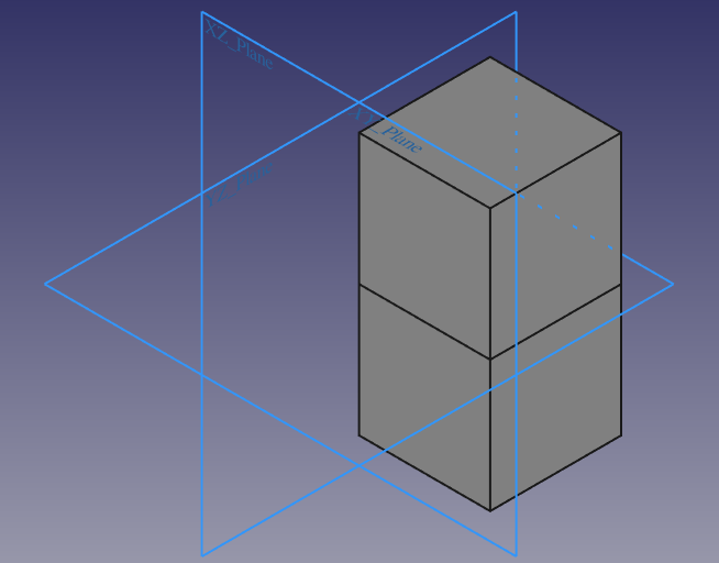
Pipe has a bit of a blocking bug right now. My test scenario involves a simple circle centered at the origin
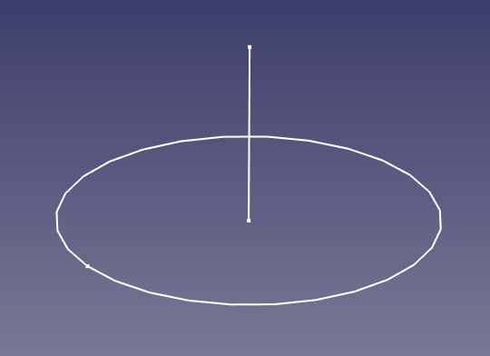
in an XY-attached sketch, serving as the base Profile, and a simple line on the Z axis in an XZ-attached sketch.
The test construction is illustrated in figure 1.
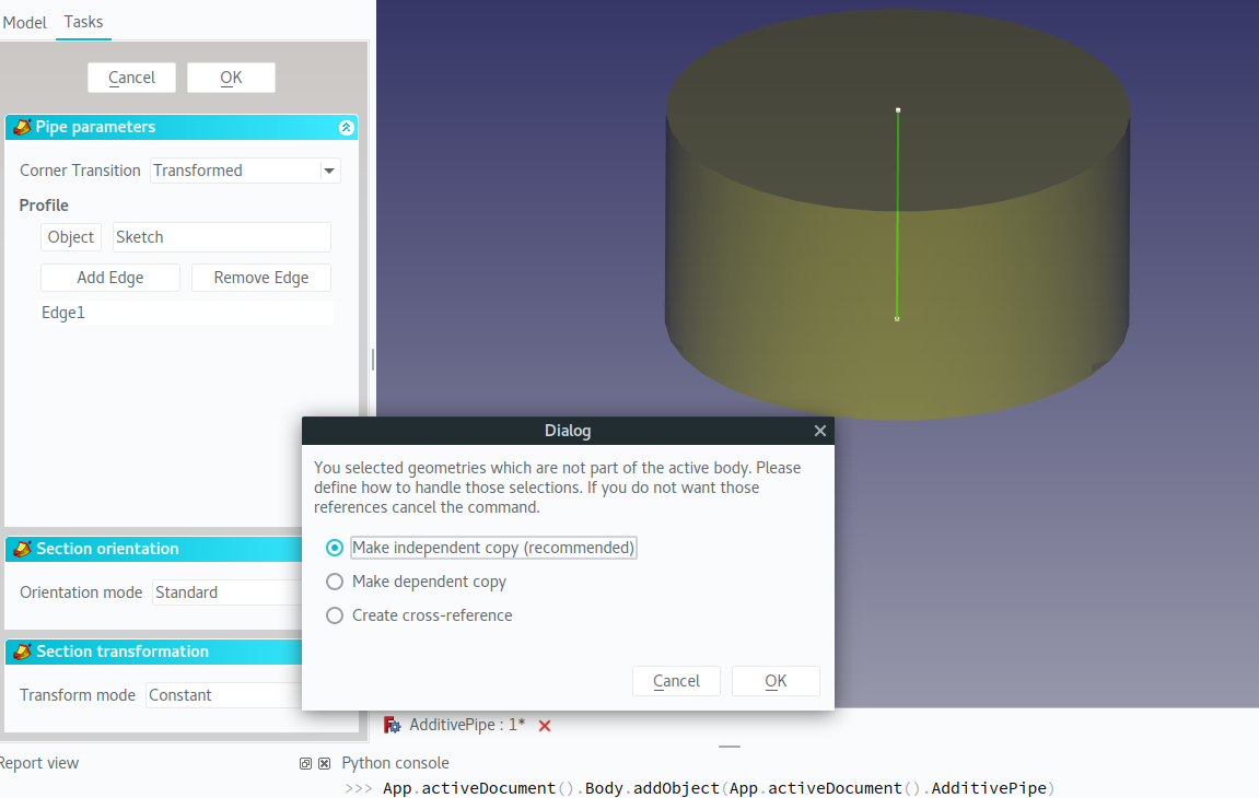
This should result in a cylinder, as the preview indicates in figure 2. For some reason, when clicking OK,
an external reference warning is being generated, and this is blocking any test constructions for PartDesign Pipe.
Figure 1. PartDesign Pipe Profile and Spine sketches which should form a simple cylinder.
Figure 2. PartDesign Pipe erroneously warning about external references.
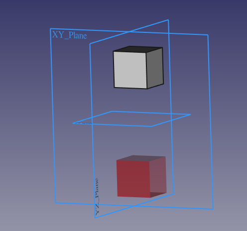
I also ran into a bug in PartDesign Revolve, which, as bugs are wont to do, ended up being two bugs.
The construction case to see them is depicted in figure 3.
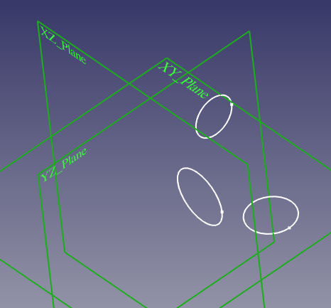
Figure 3. Simple sketches attached to the three base planes.
I attached a simple circle sketch to each of the three base planes, and offset them so they wouldn't be symmetric
with respect to the origin or any base axes. When attempting to add a Revolution with these sketches, they behave
as expected, until one attempts to revolve them about the axis which is normal to the sketch's plane. For the
XY- and YZ-attached sketches, the following error appears:
Unhandled Base::Exception caught in GUIApplication::notify.
The error message is: Rotation axis must not be perpendicular with the sketch plane
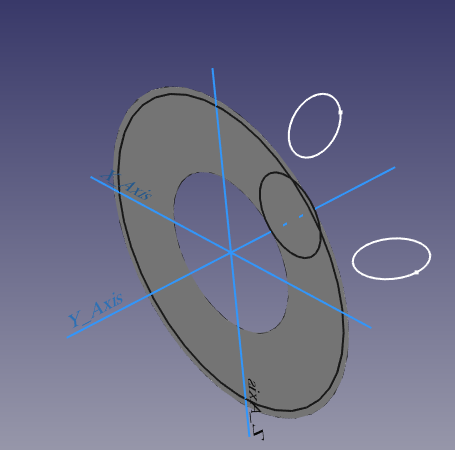
However, if one tries to revolve the XZ-attached circle, FreeCAD gives it the ol' college try, but
ends up with an awfully thin "solid":
With the four major bugs blocking the usage of PartDesign Mirrored fixed,
I started out the week exploring the now-functioning tool with the goal of getting what I call "command test coverage".
In short, this means testing major variations for tools presented to the user in the PartDesign WB.
For reference, they are depicted and categorized in figures 1 and 2,
with the newly redesigned icons made by Alexander Gryson (kudos to his major rework of all of FreeCAD's icons!)
Figure 1. Datum tools, additive/subtractive features and primitives.
Figure 2. Transformations, dressup features, and multi-body boolean operation.
The Mirrored tool takes as input feature(s) and a mirror plane, but the other transformation tools like LinearPattern and PolarPattern behave in a fundamentally similar way.
By that reasoning, I figured that tests regarding the Mirrored tool really only have two major permutations if one assumes valid input:
the case where a choice of features and plane succeeds, and one where it doesn't.
Figure 3. Success!
Figure 4. Failure...
So, I cleaned up the test case submission I started GSoC out with, testMirroredSketchCase,
and added the new case depicted in figure 4, testMirroredOffsetFailureCase.
However, I noticed both of my test cases involved Sketch-based additive features, but no additive primitives.
So, I also included testMirroredPrimitiveCase in FreeCAD PR#816.
What's nice is that besides PartDesign Mirrored now being fixed, several other transformation tools' bugs were resolved.
Altogether, the PR resolved four issues, 2235,
2248, 3006,
and 3065.
With all that wrapped up,
I moved on to adding tests for the various options for the fundamental sketch-based features Pad and Pocket.
Altogether, I added testPadToFirstCase, testPadtoLastCase, testPadToFaceCase,
and testPadTwoDimensionsCase to cover the options for PartDesign Pad.
Unfortunately, these test cases are not very interesting to look at and mostly involve 2-4 lined up cubes similar to
what figure 3 looks like.
However, for PartDesign Pad, things do get a little more interesting.
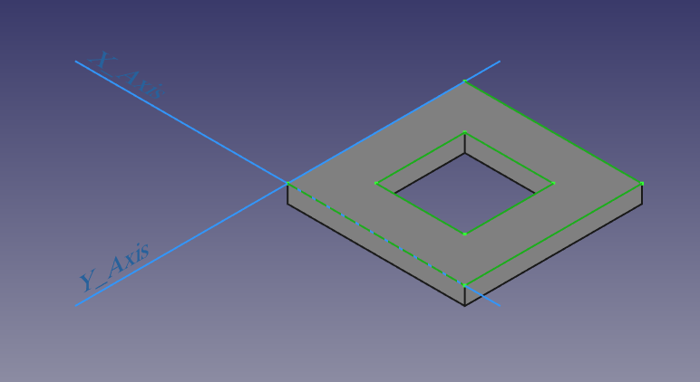
The base case is a simple reversed pad with a pocket in the middle, shown in figure 5.
Figure 5. The base Pocket test construction.
It was straightforward to add testPocketDimensionCase, testPocketThroughAllCase,
and testPocketToFirstCase.
However, covering the last Pocket option with testPocketToFaceCase is not (necessarily) so trivial.
If you refer to figure 5, you'll note that the base Pad feature is a hexahedron, or six-sided shape.
The Pocket feature adds four new faces to the overall shape, Face7 through Face10.
However, references relying on the numbering of those faces is inherently brittle and it turns out that
a particular face number OpenCASCADE > 7.0 does not correspond to the same face in a lower version, e.g.
the version used on the FreeCAD CI machines over at Travis.